పరిచయం
This manual provides essential information for the installation, operation, and maintenance of the Allen-Bradley SLC 500 1746-NI4 Series A Analog Input Module. This module is designed to convert analog signals from various sensors and devices into digital data for processing by the SLC 500 programmable logic controller (PLC) system. Proper understanding and adherence to these instructions are crucial for safe and efficient operation.
The 1746-NI4 is a high-performance analog input module, part of the SLC 500 family, known for its reliability in industrial automation environments. It supports multiple input ranges, allowing flexibility for diverse application requirements.
భద్రతా సమాచారం
Always observe standard industrial safety practices when working with electrical equipment. Disconnect all power before installing, wiring, or servicing the module. Only qualified personnel should perform installation and maintenance procedures. Failure to follow these safety guidelines could result in personal injury or equipment damage.
- అన్ని పరికరాల సరైన గ్రౌండింగ్ను నిర్ధారించుకోండి.
- సరైన సంపుటాన్ని ధృవీకరించండిtagవిద్యుత్తును కనెక్ట్ చేయడానికి ముందు e మరియు ప్రస్తుత రేటింగ్లు.
- Protect against electrostatic discharge (ESD) when handling the module.
- Do not operate the module outside its specified environmental limits.
ఉత్పత్తి ముగిసిందిview
The Allen-Bradley 1746-NI4 is an analog input module for the SLC 500 series. It features multiple input channels and configurable input ranges to accommodate various analog sensors. The module integrates seamlessly into the SLC 500 chassis.


సెటప్ మరియు ఇన్స్టాలేషన్
1. ప్రీ-ఇన్స్టాలేషన్ తనిఖీలు
- Verify that the SLC 500 chassis has an available slot for the 1746-NI4 module.
- Ensure the power supply to the SLC 500 chassis is disconnected before proceeding.
- Confirm that the module is the correct model (1746-NI4 Series A) for your application.
2 మాడ్యూల్ ఇన్స్టాలేషన్
- Carefully slide the 1746-NI4 module into an empty slot in the SLC 500 chassis until it clicks into place.
- Ensure the module is securely seated in the backplane connector.
3. వైరింగ్ కనెక్షన్లు
Refer to the wiring diagram located on the inside of the module's front cover (Figure 2) for correct terminal assignments. The 1746-NI4 supports both current and voltage inputs. Configure the input range using the DIP switches (SW1) as shown in Figure 3.
- ప్రస్తుత ఇన్పుట్: For 4-20mA or 0-20mA signals, connect the analog signal wires to the designated input terminals.
- వాల్యూమ్tagఇ ఇన్పుట్: For 0-10VDC or -10VDC to +10VDC signals, connect the analog signal wires to the designated input terminals.
- Ensure all connections are tight and secure to prevent intermittent signals.
4. DIP Switch Configuration (SW1)
The 1746-NI4 module features DIP switches (SW1) to select the desired input range for each channel. Consult the label on the module (Figure 3) for the specific switch settings corresponding to current or voltagఇ ఇన్పుట్లు.
| SW1 స్థానం | ఇన్పుట్ పరిధి | వివరణ |
|---|---|---|
| ON (Current Selection) | -20mA to +20mA | Configures the channel for current input signals. |
| OFF (Voltage Selection) | -10VDC నుండి +10VDC | Configures the channel for voltagఇ ఇన్పుట్ సిగ్నల్స్. |
Ensure that the DIP switches are set correctly for each channel based on the type of analog sensor connected.
ఆపరేటింగ్ సూచనలు
1. పవర్ అప్
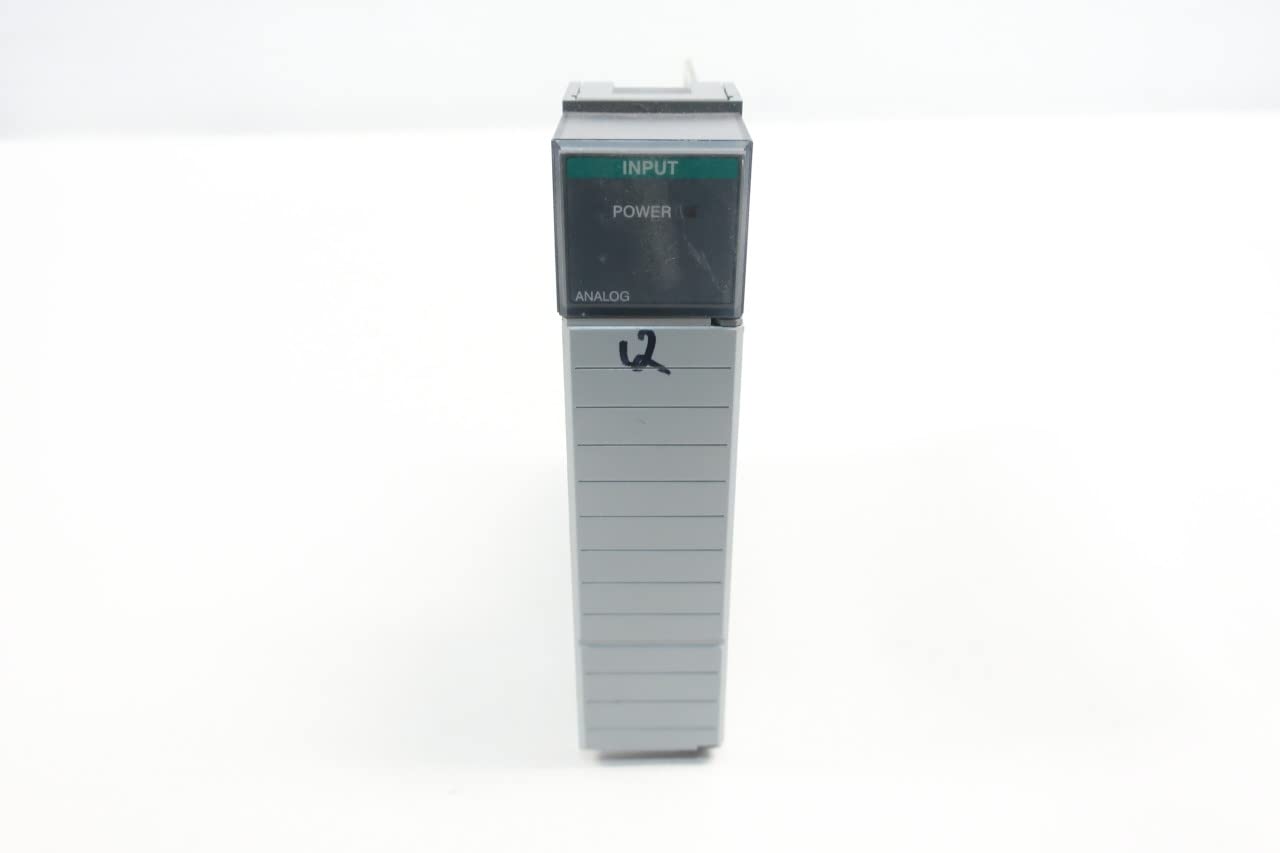
After all wiring is complete and verified, restore power to the SLC 500 chassis. The "POWER" indicator on the 1746-NI4 module (Figure 1) should illuminate, indicating proper power supply.
2. సాఫ్ట్వేర్ కాన్ఫిగరేషన్
The 1746-NI4 module requires configuration within the SLC 500 programming software (e.g., RSLogix 500). This involves:
- Adding the 1746-NI4 module to the I/O configuration tree.
- Defining the input data file (e.g., I:x.0 for the module's input data).
- Scaling analog input values to engineering units within your PLC program.
- Setting up alarm limits or other process control logic based on the analog inputs.
3. Monitoring Analog Inputs
Once configured, the analog input values can be monitored through the PLC programming software. The "INPUT" indicator on the module (Figure 1) may provide status feedback depending on the module's operational state and input activity.
నిర్వహణ
The Allen-Bradley 1746-NI4 module is designed for robust industrial use and requires minimal routine maintenance. However, periodic checks can ensure optimal performance and longevity.
- దృశ్య తనిఖీ: Periodically inspect the module and its wiring for any signs of damage, loose connections, or corrosion. Ensure the module is securely seated in the chassis.
- పర్యావరణ నియంత్రణ: Ensure the operating environment remains within the specified temperature and humidity ranges to prevent premature component failure.
- శుభ్రపరచడం: If necessary, gently clean the module's exterior with a soft, dry, lint-free cloth. Do not use solvents or abrasive cleaners.
- ఫర్మ్వేర్ నవీకరణలు: Check the official Allen-Bradley (Rockwell Automation) website for any available firmware updates for the 1746-NI4 module. Follow their instructions carefully for any update procedures.
ట్రబుల్షూటింగ్
This section provides guidance for common issues encountered with the 1746-NI4 Analog Input Module.
| సమస్య | సాధ్యమైన కారణం | పరిష్కారం |
|---|---|---|
| Module "POWER" indicator is off. | No power to chassis, module not seated correctly, faulty module. | Verify chassis power. Re-seat the module firmly. Test with a known good module if available. |
| Analog input values are incorrect or fluctuating. | Incorrect wiring, wrong DIP switch settings, sensor issue, electrical noise, faulty module. | Check wiring against diagram. Verify DIP switch settings (Table 1). Test sensor. Check for grounding issues or shielded cable requirements. Replace module if necessary. |
| Module not recognized by PLC. | Module not seated, incorrect I/O configuration in software, faulty backplane. | Re-seat module. Verify module type and slot in RSLogix 500. Check backplane integrity. |
If issues persist after following these steps, contact Allen-Bradley technical support.
స్పెసిఫికేషన్లు
Key technical specifications for the Allen-Bradley 1746-NI4 Series A Analog Input Module:
- మోడల్: 1746-NI4
- సిరీస్: A
- రకం: అనలాగ్ ఇన్పుట్ మాడ్యూల్
- ఇన్పుట్ పరిధులు: Configurable via DIP switches for Current (-20mA to +20mA) and Voltage (-10VDC to +10VDC)
- అనుకూలత: Allen-Bradley SLC 500 series controllers
- ఉత్పత్తి కొలతలు: 7.75 x 7.25 x 1.38 అంగుళాలు (సుమారుగా)
- బరువు: 7.2 ఔన్సులు (సుమారుగా)
- తయారీదారు: అలెన్ బ్రాడ్లీ
- ASIN: B016KRM48C
- SKU: D514925 (EVN)
వారంటీ మరియు మద్దతు
Allen-Bradley (Rockwell Automation) products typically come with a standard manufacturer's warranty. For specific warranty terms and conditions, please refer to the official documentation provided with your purchase or visit the Rockwell Automation website. Warranty coverage usually applies to defects in materials and workmanship under normal use.
For technical support, product documentation, software downloads, and service inquiries, please contact Rockwell Automation directly through their official website or authorized distributors. Provide your module's model number (1746-NI4) and series (A) when seeking support.
Important Links:


